- Home
- Documentation
- Community
- Projects
- Boards
- Agilex 5 SoC
- Agilex 7 SoC
- Arria 10 SoC
- Nallatech 385A - Arria 10 FPGA Network Accelerator Card
- Nallatech 385A-SoC Accelerator Card with Arria 10 FPGA
- ALARIC Instant DevKit ARRIA 10 SoC FMC IDK by REFLEX CES
- Altera Arria 10 SoC Virtual Platform
- Altera Arria 10 SoC Board
- Nallatech 510T compute acceleration card with Intel Arria 10 FPGA
- REFLEX CES Achilles Arria 10 SoC SOM
- Terasic Arria10 SoC Board : HAN Pilot Platform
- Arria V SoC
- Cyclone V SoC
- Altera Cyclone V SoC Board
- Arrow SoCKit User Manual - July 2017 Edition
- Arrow SoCKit User Manual - November 2019 Edition
- Arrow SoCKit Evaluation Board
- Atlas-SoC Development Platform
- Critical Link MitySOM-5CSx Development Kit
- Cyclone V Ethernet driver problems
- DE10-Nano Development Board
- Terasic DE10-Standard Development Kit
- Devboards DBM-SoC1 module
- Devboards DBM-SoC2 module
- EBV SoCrates Evaluation Board
- Enclustra Mercury SA1 SoC Module
- Enterpoint Drigmorn 5
- Enterpoint Larg 2
- Altera Cyclone V SoC Development Platform
- Mpression Helio SoC Evaluation Kit by Macnica
- Mpression Sodia Evaluation Board by Macnica
- ARIES Embedded - MCV System on Module
- Mpression Borax SOM Module and Development Kit by Macnica
- Enterpoint Mulldonoch 3
- Networked Pro-Audio FPGA SoC Development Kit by Coveloz
- NOVPEK™CVLite
- NOVSOM®CV
- NOVSOM®CVLite
- NovTech IoT Octopus™
- NovTech NetLeap™
- Enterpoint Raggedstone 4
- Solectrix SMARC compliant System-on-Module
- Terasic DE1-SoC Development and Education Board
- Stratix 10 SoC
- Find a Board
- News
Documentation
Similar topics
-
 Altera MAX10 10M50 Rev C Development Kit Linux Setup (ACDS version 16.1)
Altera MAX10 10M50 Rev C Development Kit Linux Setup (ACDS version 16.1)
Altera MAX10 10M50 Rev C Development Kit Linux Setup (ACDS version 16.1) -
 Altera MAX10 10M50 Rev C Development Kit Linux Setup (Sustaining)
Altera MAX10 10M50 Rev C Development Kit Linux Setup (Sustaining)
Altera MAX10 10M50 Rev C Development Kit Linux Setup (Sustaining)
Recent Changes
-
 Building Bootloader for Agilex 5
Building latest bootloaders for Agilex 5 SoC Devices
Building Bootloader for Agilex 5
Building latest bootloaders for Agilex 5 SoC Devices -
 GSRD for Agilex 7 I-Series Transceiver-SoC DevKit (4x F-Tile)
Golden System Reference Design for DK SI AGI027FB, DK SI AGI027FA and DK SI AGI027FC
GSRD for Agilex 7 I-Series Transceiver-SoC DevKit (4x F-Tile)
Golden System Reference Design for DK SI AGI027FB, DK SI AGI027FA and DK SI AGI027FC -
 Macnica Sulfur ~ Development Kit for Agilex™ 5 FPGA E-Series ~
- Ashling RiscFree Examples
-
Intel® Simics® Simulator for Intel FPGAs Release Notes
This page provides release information about the Intel® Simics® simulator for Intel FPGAs.
Table of Contents
Altera MAX10 10M50 Rev C Development Kit Linux Setup (ACDS version 17.0)
Altera MAX10 10M50 Rev C Development Kit Linux Setup (ACDS version 17.0)
- This package will work only on Linux. You will need a virtual Linux to run it on Windows.
- This package has been tested with the CentOS6.8 distribution.
- You will need Quartus II software installed in the host PC (Linux/ Windows). The following steps was executed using Quartus Prime version 17.0 std
MAX10 Development Kit Golden System Reference Design (GSRD) User Manuals
Golden Hardware Reference Design (GHRD) Overview
The MAX10 Development Kit Golden Hardware Reference Design (GHRD) is an important part of the Golden System Reference Design (GSRD) User Manuals and consists of the following components:- Nios II Gen2 Processor with memory management unit (MMU) enabled
- DDR3 SDRAM controller
- Quad SPI controller
- RGMII Gigabit Ethernet
- Modular SGDMA
- Modular ADC
- UART
- PIO access to button and LED
- System clock
- On-chip Memory
- System ID
- JTAG for debugging purposes

 The MAX10 development kit GHRD demonstrated the Triple Speed Ethernet (TSE) soft IP together with the Nios II Gen2 Processor that support memory management unit (MMU). Modular Scatter-Gather Direct Memory Access (mSGDMA) IP is used for data transfer within the system.
The following section provides guidance and step by step flow for software developers to setup Linux operating system on MAX10 development kit based on MAX10 GHRD design.
The MAX10 development kit GHRD demonstrated the Triple Speed Ethernet (TSE) soft IP together with the Nios II Gen2 Processor that support memory management unit (MMU). Modular Scatter-Gather Direct Memory Access (mSGDMA) IP is used for data transfer within the system.
The following section provides guidance and step by step flow for software developers to setup Linux operating system on MAX10 development kit based on MAX10 GHRD design.
Demonstrate Usage
Setting up board to program Quad SPI Flash
 This setup is for Altera MAX10 10M50 Rev C development kit. Setup SW2 switch to follow the diagram above. Make sure VTAP Bypass is in ON position and leave the rest in OFF position.
Program POF (linux image) into Quad SPI Flash
Note: You will need to program the parallel flash loader into the MAX10 device before programming the Quad SPI flash. Connect USB cable from host PC to J12 on the MAX10 development kit. Power on the development kit. Open Quartus II software in the host PC and open Quartus II Programmer (Tools >> Programmer). Click on "Hardware Setup" and under "Currently selected hardware:", select the USB-BlasterII hardware. Click 'Close' when you are done. Click on "Auto Detect" and select your device. Click 'OK' when you are done.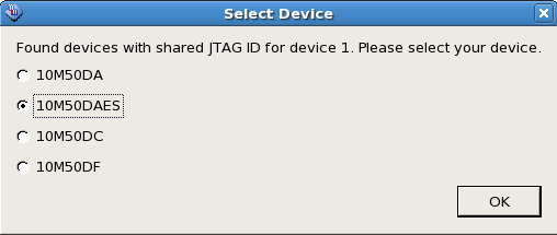
Program Parallel Flash Loader into MAX10 Device
Download max10_qpfl.sof from attachment. Right click on the MAX10 device and select "Edit > Change File". Choose the downloaded max10_qpfl.sof file. Check MAX10 device under Program/Configure and click 'Start' to start programming.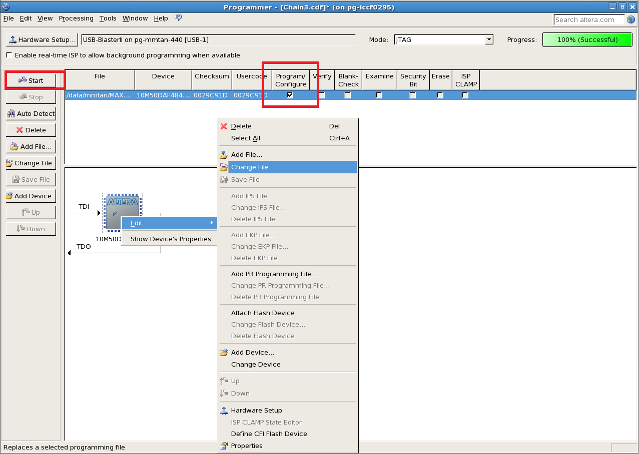 Click on "Auto Detect" after successfully programmed max10_qpfl.sof file. Click 'Yes' if you are asked to overwrite the existing settings. A new QSPI flash device will be shown on screen as below:

Program Linux Image into Quad SPI Flash
Download vmlinux_rootfs.pof from attachment. Right click on the QSPI device and select "Edit > Change File". Choose the downloaded vmlinux_rootfs.pof file. Check rootfs.hex and vmlinux.hex under Program/Configure column and click 'Start' to start programming.Program GHRD POF into MAX10
After successfully programmed Linux Image into Quad SPI flash, download ghrd_10m50daf484c6ges.pof from attachment. Right click on the MAX10 device and select "Edit > Change File". Choose the downloaded ghrd_10m50daf484c6ges.pof file. Check MAX10's CFM0 and UFM under Program/Configure column and click 'Start' to start programming.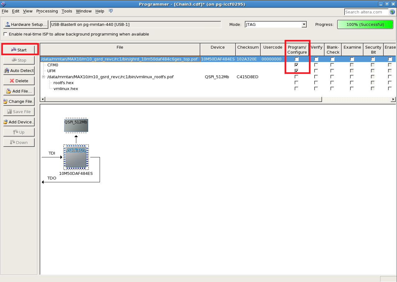
Booting MAX10 development kit with Linux
Power off development kit after POF files are programmed. Swap USB cable from J12 (USB) to J11 (UART). Open UART terminal on host PC (e.g: PuTTY, Tera Term in Windows or Minicom in Linux) to connect UART. Set the UART terminal with the following settings:-
Baud rate: 115200
-
Data: 8 bit
-
Parity: none
-
Stop: 1 bit
-
Flow control: none

Running ADC demonstration on MAX10 development kit
After login into the Nios II Linux with "root" access, you can demonstrate the ADC functionality using adc_demo.sh script which is stored at the root location. Run the following command to execute the script to obtain the ADC raw value:# ./adc_demo.sh
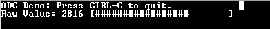 You can change the ADC value by shifting the "3362" blue potentiometer on the MAX10 development kit.
Note:
If you are seeing "Permission denied" message when trying to execute the script, change the script permission by running the following command at root location:
You can change the ADC value by shifting the "3362" blue potentiometer on the MAX10 development kit.
Note:
If you are seeing "Permission denied" message when trying to execute the script, change the script permission by running the following command at root location:
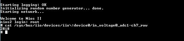
# chmod 777 adc_demo.shAlternatively, you can also use the following command to capture the raw ADC data:
# cat /sys/bus/iio/devices/iio\:device0/in_voltage0_adc1-ch7_raw
Building SOF
Compile GHRD design using Quartus II
Download ghrd_10m50daf484c6ges.tar.gz from attachment. Restore the archived project to your host PC$ tar xvf ghrd_10m50daf484c6ges.tar.gzOpen Quartus II software from the host PC. Select "File >> Open Project" and open the ghrd_10m50daf484c6ges.qpf file. Compile the Quartus project (Processing >> Start Compilation) . Use the POF file generated in "<project_folder>/output_files" to program into MAX10 device. For programming GHRD design into MAX10 device, refer to Program GHRD POF into MAX10.
Compile qpfl design using Quartus II
You can refer to Altera MAX10 10M50 QPFL design.Building POF with Nios II Linux MMU kernel image
Setting up toolchain
Go to the link below, select Altera Nios II Processor GNU/Linux release, download and install Sourcery CodeBench Lite. There are two type of toolchains, generic syscall ABI compatible toolchain and non-generic syscall ABI compatible toolchain and each only work for the targeted kernel (generic or non-generic syscall ABI compatible kernel). These two toolchains are not binary compatible, this means you need to recompile all the source files if you switching toolchain between them (e.g: kernel, rootfs, applications and etc) Note: MAX10 design is using kernel version socfpga-3.10-ltsi. Please use Sourcery CodeBench Lite 2013.05-43 toolchain.Sourcery CodeBench Lite 2014.05-47 and above
This toolchain is with generic syscall ABI.
Example supported kernel: linux-socfpga/github (kernel v4.0 and above), master/kernel.org (kernel v3.19 and above)
Sourcery CodeBench Lite 2013.05-43
This toolchain is with non generic syscall ABI
Example supported kernel: socfpga-3.18 and version prior 3.18 in linux-socfpga.git
$ /bin/sh <Nios II Linux GNU installer>.binThe toolchain is located in the CodeSourcery folder, add the toolchain to your PATH. At the same time, set the Nios II architecture and cross compiler for building source codes.
$ export PATH=/<your path>/CodeSourcery/Sourcery_CodeBench_Lite_for_Nios_II_GNU_Linux/bin/:$PATH
$ export ARCH=nios2
$ export CROSS_COMPILE=nios2-linux-gnu-
To confirm the toolchain is added properly, type "echo $PATH". To confirm the architecture and cross compiler are added properly, type "echo $ARCH" and "echo $CROSS_COMPILE" respectively. Note: The ARCH and CROSS_COMPILE parameters are tied to each terminal session. Please remember to set these parameters whenever you change a new terminal for building source codes.
Building root filesystem
Buildroot is used to build the root filesystem for Nios II Linux. Download Buildroot source files from Buildroot GIT.$ git clone http://github.com/buildroot/buildroot.git $ cd buildroot $ git checkout 2015.02Download Nios II config file for Buildroot: nios2_defconfig. Add this file to <buildroot_top_directory>/configs. Go to Buildroot top directory and configure Buildroot for Nios II:
$ make nios2_defconfigTo build:
- You need to be connected to the network before make as the script must download and install packages.
$ makeOutput file name : rootfs.jffs2, rootfs.cpio, rootfs.tar Output directory : <Buildroot_top_directory>/output/images In order to obtain the adc_demo.sh for ADC test, get the file from the link https://releases.rocketboards.org/2015.10/gsrd/tools/adc_demo.sh, then copy it to the "<buildroot_top_directory>/output/target/root" folder AFTER you perform the steps above and rebuild the root filesystem again. At the buildroot top directory, run the following commands:
$ wget https://releases.rocketboards.org/2015.10/gsrd/tools/adc_demo.sh
$ cp adc_demo.sh output/target/root
$ make
You can optionally get the adc_demo.sh file after you boot into the Linux with the vanilla root filesystem built above and run the command:
$ wget https://releases.rocketboards.org/2015.10/gsrd/tools/adc_demo.shNote: You might encounter "missing makeinfo" error during the build if you are running on a new Linux machine. To resolve this issue, install texinfo: a) For CentOS Linux machine: $ sudo yum install texinfo b) For Ubuntu Linux machine: $ sudo apt-get install texinfo
Building Nios II Linux kernel
Max10 design is using kernel version: socfpga-3.10-ltsi. Download the latest Linux kernel source files from https://github.com/altera-opensourceusing git.$ git clone https://github.com/altera-opensource/linux-socfpga.git
$ cd linux-socfpga
$ git checkout -b test_branch ACDS17.0_REL_M10_GSRD_PR
Note: Replace test_branch with the name of the branch you want to use locally.
Go to Linux top directory and configure Linux kernel for Nios II.
For 10m50 design, make sure 10m50_defconfig file is available in <Linux_kernel_top_directory>/arch/nios2/configs.
Install the 10m50_defconfig patch:
$ make 10m50_defconfig10m50 design is using static device tree, make sure 10m50_devboard.dts file is available in <Linux_kernel_top_directory>/arch/nios2/boot/dts. To build vmlinux:
$ make vmlinuxOutput file name : vmlinux Output directory : <Linux_kernel_top_directory>
Generate POF with Linux image
Before proceeding this step, please make sure Quartus 15.0 is installed and path is setup properly to access nios2eds/bin folder to access command elf2flash and nios2-elf-objcopy. This procedure is to generate a POF file to be programmed into Quad SPI with linux image embedded inside. POF is generated with Quartus Convert Programming File GUI (File >> Convert Programming File) and this application only accept hex image. Linux image generated from Building Nios II Linux kernel above has to be converted to hex format. This is a 2-step procedure. First, at Linux_kernel_top_directory, create Linux SREC in flash format (vmlinux.flash) from Linux ELF (vmlinux) and inject boot copier in front of Linux image. vmlinux.flash is generated in the same folder.$ elf2flash --base=0x0 --input=vmlinux --end=0xfffffff --reset=0x0 --boot=$SOPC_KIT_NIOS2/components/altera_nios2/boot_loader_cfi.srecThen convert Linux SREC to HEX format
$ nios2-elf-objcopy -O ihex vmlinux.flash vmlinux.hexRoot filesystem generated from "building root filesystem" above also has to be converted to hex format. at <Buildroot_top_directory>/output/images, convert JFFS2 to HEX format.
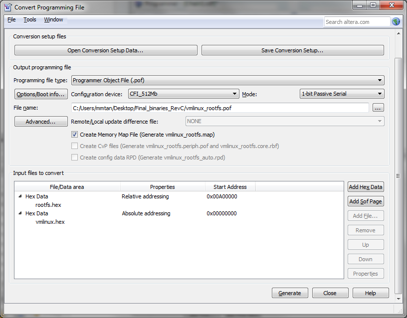
$ nios2-elf-objcopy -O ihex -I binary rootfs.jffs2 rootfs.hexNext step is to convert hex files to POF using Quartus Convert Programming File GUI (File >> Convert Programming File) NOTE: quartus.ini is needed to program Quad SPI. Please download quartus.ini from attachment and copy to Quartus II tool directory or project directory. If the quartus.ini file is copied into the project directory, open the quartus project in Quartus II before opening the Convert Programming File GUI. Without this quartus.ini file, incompatible POF will be generated.
- Programming file type, select Programmer Object File (.pof).
- Configuration device, select CFI_512 Mb.
- Select the output path for the POF file under "File name:" column.
- Remove the SOF Page_0 in the "Input files to convert" section.
- Adding ROOTFS HEX. Click on "Add Hex Data", select relative addressing and set starting address at 0x00A00000, choose "rootfs.hex" generated above.
- Setting starting address at 0x00A00000 allocates 54Mb of the flash size for the root filesystem.
- Adding LINUX HEX. Click on "Add Hex Data", select absolute addressing and choose "vmlinux.hex" generated above.
- Kernel is at top half of the flash device with 10Mb of flash size.
- Click "Generate" button to generate POF file.
 Follow the procudure in usage demonstation above to program POF and boot linux on MAX10 development kit.
Known Issues
- Setup and Hold time violation paths report in Time Quest on DDR3 ports are known issue and there is an ERRATA for this. The device is functioning ok with time violation paths.
© 1999-2024 RocketBoards.org by the contributing authors. All material on this collaboration platform is the property of the contributing authors.
This website is using cookies. More info.
That's Fine