Arria 10 SoC Golden System Reference Design
Overview
The Golden System Reference Design (GSRD) provides a set of essential hardware and software system components that can be used as a starting point for various custom user designs.
The A10 GSRD consists of:
- Arria 10 SoC Development Kit
- Golden Hardware Reference Design (GHRD)
- Linux release
- U-Boot release
- Linux sample drivers
- Linux sample applications
Prerequisites
The following are required in order to be able to fully exercise the A10 GSRD:
- Arria 10 SoC Development Kit, rev. C, including
- DDR4 HILO memory card
- Micro SD boot flash card
- Mini USB cable for serial output
- Micro USB cable for on-board Intel FPGA Download Cable II
- Micro SD card (4GB or greater)
- Host PC with
- Linux - Ubuntu 20.04 was used to create this page, other versions and distributions may work too
- Serial terminal (for example Minicom on Linux and TeraTerm or PuTTY on Windows)
- Micro SD card slot or Micro SD card writer/reader
- Intel Quartus Prime Pro Edition v24.1 (v24.1 for rebuilding the current monthly GSRD release)
- Local Ethernet network, with DHCP server (will be used to provide IP address to the board)
Note that the U-Boot and Linux compilation, Yocto compilation and creating the SD card image require a Linux host PC. The rest of the operations can be performed on either a Windows or Linux host PC.
Release Contents
Intel FPGA HPS Embedded Software Release Notes
The Intel FPGA HPS Embedded Software release notes can be accessed from the following link:
https://www.rocketboards.org/foswiki/Documentation/IntelFPGAHPSEmbeddedSoftwareRelease
Latest Binaries Release Content
The release files are accessible at
https://releases.rocketboards.org/2024.04/gsrd/a10_gsrd/ and contain the following:
| File |
Description |
|---|
| Image |
Prebuilt Linux kernel image |
| zImage |
Prebuilt Compressed Linux kernel image |
| a10_soc_devkit_ghrd_QPDS-24.1pro-24.1std.tar.gz |
Hardware project, including precompiled SOF |
| hps.xml |
Quartus handoff file to be used by U-Boot |
| fit_spl_fpga.itb |
Prebuilt FPGA Configuration files, used by SPL or U-Boot |
| fit_uboot.itb |
Prebuilt U-Boot image |
| ghrd_10as066n2.core.rbf |
Prebuilt FPGA core configuration file |
| ghrd_10as066n2.periph.rbf |
Prebuilt FPGA periphery configuration file |
| ghrd_10as066n2.sof |
Prebuilt FPGA configuration file |
| sdimage.tar.gz |
Prebuilt SD Card Image |
| sdimage.tar.gz.md5sum |
Checksum for prebuilt SD Card Image |
| socfpga_arria10_socdk_sdmmc.dtb |
Prebuilt Linux Device Tree Binary |
| socfpga_arria10_ghrd.dtsi |
Linux Device Tree Source Include File |
| socfpga_arria10_socdk.dtsi |
Linux Device Tree Source Include File |
| u-boot-splx4.sfp |
Prebuilt SPL image file |
| u-boot.img |
Prebuilt U-Boot image file |
| rootfs/console-image-minimal-arria10.tar.gz |
Prebuilt small root filesystem |
| rootfs/gsrd-console-image-arria10.tar.gz |
Prebuilt GSRD root filesystem |
| rootfs/xvfb-console-image-arria10.tar.gz |
Prebuilt Frame Buffer root filesystem |
Before downloading the hardware design please read the agreement in the link
https://www.intel.com/content/www/us/en/programmable/downloads/software/license/lic-prog_lic.html
Source Code
The source code is also included on the SD card in the Linux rootfs path
/home/root:
| File |
Description |
|---|
| linux-socfpga-v6.1.68-lts-src.tar.gz |
Source code for Linux kernel |
| u-boot-socfpga_v2023.10-src.tar.gz |
Source code for U-Boot |
| arm-trusted-firmware-v2.10.0-src.tar.gz |
Source code for Arm Trusted Firmware |
Latest Source Code Release Contents - Branches and Commit IDs
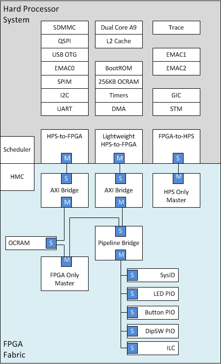
GHRD Overview
The GHRD is an important part of the GSRD and consists of the following components:
- Dual-core ARM Cortex*-A9 MPCore* Hard Processor System (HPS)
- Hard Memory Controller (HMC)
- Two user push-button inputs
- Four user DIP switch inputs
- Four user I/O for LED outputs
- 256KB of FPGA on-chip memory
- JTAG to Avalon Master Bridges
- Interrupt Latency Counter
- System ID

The GHRD allows hardware engineers to access each peripheral in the FPGA portion of the SoC with System Console, through the JTAG master module. This signal-level access is independent of the driver readiness of each peripheral.
Cortex-A9 MPU Address Maps
This sections presents the address maps as seen from the MPU (Cortex-A9) side.
HPS-to-FPGA Address Map
The memory map of soft IP peripherals, as viewed by the microprocessor unit (MPU) of the HPS, starts at HPS-to-FPGA base address of 0xC000_0000. The following table lists the offset from 0xC000_0000 of each peripheral in the FPGA portion of the SoC.
| Peripheral |
Address Offset |
Size (bytes) |
Attribute |
|---|
| onchip_memory2_0 |
0x0 |
256K |
On-chip RAM as scratch pad |
Lightweight HPS-to-FPGA Address Map
The memory map of system peripherals in the FPGA portion of the SoC as viewed by the MPU, which starts at the lightweight HPS-to-FPGA base address of 0xFF20_0000, is listed in the following table.
| Peripheral |
Address Offset |
Size (bytes) |
Attribute |
|---|
| sysid_qsys |
0x0000_0000 |
8 |
Unique system ID |
| led_pio |
0x0000_0010 |
8 |
LED output |
| button_pio |
0x0000_0020 |
8 |
Push button input |
| dipsw_pio |
0x0000_0030 |
8 |
DIP switch input |
| ILC |
0x0000_0100 |
256 |
Interrupt latency counter |
JTAG Master Address Map
There are two JTAG master interfaces in the design, one for accessing non-secure peripherals in the FPGA fabric, and another for accessing secure peripherals in the HPS through the FPGA-to-HPS interface.
The following table lists the address of each peripheral in the FPGA portion of the SoC, as seen through the non-secure JTAG master interface.
| Peripheral |
Address Offset |
Size (bytes) |
Attribute |
|---|
| sysid_qsys |
0x0000_0000 |
8 |
Unique system ID |
| led_pio |
0x0000_0010 |
8 |
4 LED outputs |
| button_pio |
0x0000_0020 |
8 |
2 push button inputs |
| dipsw_pio |
0x0000_0030 |
8 |
4 DIP switch inputs |
| ILC |
0x0000_0100 |
256 |
Interrupt latency counter |
Interrupt Routing
The HPS exposes 64 interrupt inputs for the FPGA logic. The following table lists the interrupt connections from soft IP peripherals to the HPS interrupt input interface.
| Peripheral |
Interrupt Number |
Attribute |
|---|
| dipsw_pio |
f2h_irq0[0] |
4 DIP switch inputs |
| button_pio |
f2h_irq0[1] |
2 push button inputs |
The interrupt sources are also connected to an interrupt latency counter (ILC) module in the system, which enables System Console to be aware of the interrupt status of each peripheral in the FPGA portion of the SoC.
Typical HPS Boot Flow
The GSRD boot flow includes the following stages:
- Boot ROM
- U-Boot
- Operating System (OS)
- Application
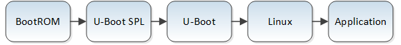
The following table presents a short description of the different boot stages:
| Stage |
Description |
|---|
| Boot ROM |
Performs minimal configuration and loads U-Boot into 256KB OCRAM |
| U-Boot SPL |
Configures IO, FPGA, brings up SDRAM |
| U-Boot |
Loads Linux kernel |
| Linux |
Operating system |
| Application |
User application |
For more information, please refer to
Arria 10 SoC Boot User Guide and
Intel Arria 10 Hard Processor System Technical Reference Manual (Booting and Configuration chapter).
Running GSRD with Pre-Built Binaries
Booting Linux Using SD Card Image
This section will guide you to boot the Linux with the Arria 10 SoC device according to the
HPS Boot Flow.
Creating SD Card
This section explains how to create the SD card necessary to boot Linux, using the SD card image available with the pre-built Linux binaries package. Once the SD card has been created, insert the card into the SD slot of the Micro SD daughter card.
Creating SD Card on Linux
1. Download and extract the SD card image:
wget https://releases.rocketboards.org/2024.04/gsrd/a10_gsrd/sdimage.tar.gz
tar xf sdimage.tar.gz
The extacted file is named
gsrd-console-image-arria10.wic.
2. Determine the device associated with the SD card on the host by running the following command before and after inserting the card.
$ cat /proc/partitions
Let's assume it is /dev/sdx.
3. Use
dd utility to write the SD image to the SD card.
$ sudo dd if=gsrd-console-image-arria10.wic of=/dev/sdx bs=1M
Note we are using
sudo to be able to write to the card.
4. Use
sync utility to flush the changes to the SD card.
$ sudo sync
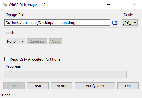
Creating SD Card on Windows
1. Download and uncompress the SD card image from
https://releases.rocketboards.org/2024.04/gsrd/a10_gsrd/sdimage.tar.gz
The extacted file is named
gsrd-console-image-arria10.wic.
2. Rename the wic file as
sdimage.img
3. Use Win32DiskImager to write the image to the SD card. The tool can be downloaded from
https://sourceforge.net/projects/win32diskimager/files/latest/download

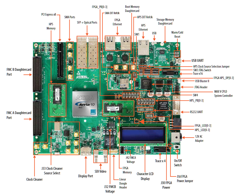
Configuring Board
This section presents the necessary board settings in order to run the GSRD on the Arria 10 SoC development board.

First, confirm the following:
- DDR4 memory card is installed on the HPS Memory slot
- Micro SD boot flash card is installed on the Boot Memory Daughtercard slot
Then, the board switches need to be configured as follows:
- SW1: OFF-OFF-ON-ON
- SW2: All OFF
- SW3: OFF-ON-ON-ON-ON-OFF-OFF-OFF
- SW4: All OFF
Also, the board jumpers need to be configured as follows:
- Leave the SD Card boot card jumpers placed in their default configuration
- On the development board:
- Place jumpers J16, J17
- BSEL0(J3) = 1 (left)
- BSEL1(J4) = 0 (right)
- BSEL2(J5) = 1 (left)
- Leave all other board jumpers unplaced
Configuring Serial Connection
The board has a built-in FTDI USB to serial converter chip that allows the host computer to see the board as a virtual serial port. Ubuntu, CentOS and other modern Linux distributions have built-in drivers for the FTDI USB to serial converter chip, so no driver installation is necessary on those platforms. On Windows, the SoC EDS installer automatically installs the required drivers if necessary.
The serial communication parameters are:
- Baud rate: 115200
- Parity: None
- Flow control: None
- Stop bits: 1
On Windows, utilities such as TeraTerm or PuTTY can be used to connect the board. They are easily configured from the tool menus.
On Linux, the Minicom utility can be used. Here is how to configure it:
1. The virtual serial port is usually named
/dev/ttyUSB0. In order to determine the device name associated with the virtual serial port on your host PC, please perform the following:
- Use the following command to determine which USB serial devices are already installed:
ls /dev/ttyUSB*
- Connect mini USB cable from J10 to the PC. This will enable the PC to communicate with the board, even if the board is not powered yet.
- Use the ls /dev/ttyUSB* command again to determine which new USB serial device appeared.
2. Install Minicom application on host PC, if not already installed.
- On CentOS, use sudo yum install minicom
- On Ubuntu, use sudo apt-get install minicom
3. Configure Minicom
sudo minicom -s
Under
Serial Port Setup choose the following:
- Serial Device: /dev/ttyUSB0 (edit to match the system as necessary)
- Bps/Par/Bits: 115200 8N1
- Hardware Flow Control: No
- Software Flow Control: No
- Hit [ESC] to return to the main configuration menu
Select
Save Setup as dfl to save the default setup. Then select
Exit.
Booting Linux
This section presents how to boot Linux on the board. The required steps are:
1. Start serial terminal (when using Minicom it will connect using the selected settings, for others connect manually).
2. Power up the board.
3. U-Boot SPL is ran (two banners are displayed)
4. U-Boot is ran
5. Linux boots.
6. The IP address of the target board will be displayed on the first line of the LCD display. Note that the IP address is displayed only at boot time, it is not updated if the IP address is changed later, for example by the user.
7. Login using 'root' and no password.
U-Boot SPL 2022.01 (Jul 14 2022 - 04:47:18 +0000)
FPGA: Checking FPGA configuration setting …
FPGA: Start to program peripheral/full bitstream …
FPGA: Early Release Succeeded.
FPGA: Checking FPGA configuration setting …
FPGA: Start to program peripheral/full bitstream …
FPGA: Early Release Succeeded.

U-Boot SPL 2022.01 (Jul 14 2022 - 04:47:18 +0000)
DDRCAL: Success
DDRCAL: Scrubbing ECC RAM (1024 MiB).
DDRCAL: SDRAM-ECC initialized success with 148 ms
FPGA: Checking FPGA configuration setting …
FPGA: Skipping configuration …
WDT:   Started watchdog@ffd00300 with servicing (10s timeout)
Trying to boot from MMC1

U-Boot 2022.01 (Jul 14 2022 - 04:47:18 +0000)socfpga_arria10

CPU:   Altera SoCFPGA Arria 10
BOOT:  SD/MMC External Transceiver (1.8V)
Model: Altera SOCFPGA Arria 10
DRAM:  1 GiB
WDT:   Started watchdog@ffd00300 with servicing (10s timeout)
MMC:   dwmmc0@ff808000: 0
Loading Environment from MMC… *** Warning - bad CRC, using default environment

In:    serial
Out:   serial
Err:   serial
Model: Altera SOCFPGA Arria 10
Net:
Warning: ethernet@ff800000 (eth0) using random MAC address - 1a:4c:fe:b0:88:ae
eth0: ethernet@ff800000
Hit any key to stop autoboot:  0
Failed to load 'u-boot.scr'
15024780 bytes read in 717 ms (20 MiB/s)
Full Configuration Succeeded.
FPGA: Enter user mode.
switch to partitions #0, OK
mmc0 is current device
Scanning mmc 0:1…
Found /extlinux/extlinux.conf
Retrieving file: /extlinux/extlinux.conf
1:      Arria10 SOCDK SDMMC
Retrieving file: /extlinux/../zImage
append: root=/dev/mmcblk0p2 rootwait rw earlyprintk memmap=16M$0x3F000000 console=ttyS0,115200n8
Retrieving file: /extlinux/../socfpga_arria10_socdk_sdmmc.dtb
Kernel image @ 0x1000000 [ 0x000000 - 0x5993a0 ]
## Flattened Device Tree blob at 02000000
   Booting using the fdt blob at 0x2000000
   Loading Device Tree to 09ff5000, end 09fff26c … OK

Starting kernel …

Deasserting all peripheral resets
[    0.000000] Booting Linux on physical CPU 0x0
[    0.000000] Linux version 5.15.30-altera (oe-user@oe-host) (arm-poky-linux-gnueabi-gcc (GCC) 11.3.0, GNU ld (GNU Binutils) 2.38.20220516) #1 SMP Fri Jun 24 03:52:26 UTC 2022
[    0.000000] CPU: ARMv7 Processor [414fc091] revision 1 (ARMv7), cr=10c5387d
[    0.000000] CPU: PIPT / VIPT nonaliasing data cache, VIPT aliasing instruction cache
[    0.000000] OF: fdt: Machine model: Altera SOCFPGA Arria 10

…

[  OK  ] Started Network Configuration.
[  OK  ] Reached target Network.
[  OK  ] Started NFS status monitor for NFSv2/3 locking..
[  OK  ] Started Hostname Service.
[    9.443394] random: crng init done
[  OK  ] Finished Load/Save Random Seed.
[   11.044930] socfpga-dwmac ff800000.ethernet eth0: Link is Up - 1Gbps/Full - flow control rx/tx
[   11.065488] IPv6: ADDRCONF(NETDEV_CHANGE): eth0: link becomes ready

Poky (Yocto Project Reference Distro) 4.0.2 arria10 ttyS0

arria10 login: root
Last login: Fri Apr 29 03:03:53 +0000 2022 on /dev/ttyS0.
root@arria10:~#
Running Sample Linux Applications
The GSRD includes a number of sample Linux applications that help demonstrate some of the features of the platform:
- Display Hello World message
- Control LEDs
- Detect interrupts from push buttons and DIP switches
The sample applications can be used as a starting point for users to write their own applications that interact with software IP through Linux drivers.
Prerequisites
1. Boot Linux on the target board as described in
Booting Linux. You will not need to use the serial terminal if you plan on using ssh connection.
2. Connect to the board using one of the following options:
3. In serial console, or ssh client console, change current folder to be
/home/root/altera. This is where the application binaries are stored.
root@arria10:~# cd /home/root/intelFPGA/
Display Hello World Message
Run the following command to display the Hello World message on the console:
root@arria10:~/intelFPGA# ./hello
Hello SoC FPGA!
Exercise Soft PIO Driver for LED Control
The following LEDs are exercised:
| LED Number |
Corresponding Board LED |
|---|
| 0 |
D26 |
| 1 |
D25 |
| 2 |
D28 |
| 3 |
D27 |
1. In order to blink an LED in a loop, with a specific delay in ms, run the following command:
./blink <led_number> <delay_ms>
- The led_number specifies the desired LED, and is a value between 0 and 3.
- The delay_ms is a number that specifies the desired delay in ms between turning the LED on and off.
2. In order to turn an individual LED on or off, run the following command:
./toggle <led_number> <state>
- The led_number specifies the desired LED, and is a value between 0 and 3.
- The state needs to be 0 to turn the LED off, and 1 to turn the LED on.
3. In order to scroll the FPGA LEDs with a specific delay, please run the following command:
./scroll_client <delay>
The
delay specifies the desired scrolling behavior:
- delay > 0 - specify new scrolling delay in ms, and start scrolling
- delay < 0 - stop scrolling
- delay = 0 - display current scroll delay
Register Interrupts and Call Interrupt Service Routine
In order to register an interrupt handler to a specific GPIO, you will first need to determine the GPIO number used.
1. Open the Linux Device Tree
socfpga_arria10_ghrd.dtsi file and look up the labels for the DIP switches and Push button GPIOs:
    button_pio: gpio@0x100000020 {
        compatible = "altr,pio-1.0";
        reg = <0xff200020 0x10>;
        interrupt-parent = <&intc>;
        interrupts = <0 19 1>;
        altr,gpio-bank-width = <4>;
        altr,interrupt-type = <2>;
        altr,interrupt_type = <2>;
        edge_type = <1>;
        level_trigger = <0>;
        resetvalue = <0>;
        #gpio-cells = <2>;
        gpio-controller;
    };

   dipsw_pio: gpio@0x100000030 {
        compatible = "altr,pio-1.0";
        reg = <0xff200030 0x10>;
        interrupt-parent = <&intc>;
        interrupts = <0 20 1>;
        altr,gpio-bank-width = <4>;
        altr,interrupt-type = <3>;
        altr,interrupt_type = <3>;
        edge_type = <2>;
        level_trigger = <0>;
        resetvalue = <0>;
        #gpio-cells = <2>;
        gpio-controller;
    };
Determine which of the GPIO entries from
/sys/class/gpio/ matches the offsets by searching for the address in the label entry.
2. Run the following to determine the GPIO numbers for the DIP switches
root@arria10:~#  grep -r "0x100000030" /sys/class/gpio/gpiochip*/label
/sys/class/gpio/gpiochip1952/label:/soc/gpio@0x100000030
This means that the GPIOs 1952 .. 1955 are allocated to the DIP switches (there are 4 of them).
3. Run the followinig to determine the GPIO numbers for the pushbuttons
root@arria10:~#  grep -r "0x100000020" /sys/class/gpio/gpiochip*/label
/sys/class/gpio/gpiochip1984/label:/soc/gpio@0x100000020
This means that the GPIOs 1984, 1985 are allocated to the push buttons (there are 2 of them).
4. Register interrupt for one of the dipswiches, using the appropriate GPIO number, as determined in a previous step:
root@arria10:~#  modprobe gpio_interrupt gpio_number=1952 intr_type=3
[  269.876015] gpio_interrupt: loading out-of-tree module taints kernel.
[  269.887086] Interrupt for GPIO:1952
[  269.887086]  registered
5. Toggle the dipswitch a few times, you will see messages from the interrupt handler
[  269.882892] Interrupt happened at gpio:1952
[  279.913910] Interrupt happened at gpio:1952
[  279.923967] Interrupt happened at gpio:1952
[  280.700461] Interrupt happened at gpio:1952
6. Remove the driver
root@arria10:~# rmmod gpio_interrupt
7. Register the pushbutton interrupt, using the appropriate GPIO number as determine on a previous step
root@arria10:~# modprobe gpio_interrupt gpio_number=1984 intr_type=2
[  317.445090] Interrupt for GPIO:1984
[  317.445090]  registered
8. Push the pusbutton a few times, you will see interrupt handler messages
[  325.824591] Interrupt happened at gpio:1984
[  326.428601] Interrupt happened at gpio:1984
[  326.966495] Interrupt happened at gpio:1984
[  327.554294] Interrupt happened at gpio:1984
9. Once done, remove the handler
root@arria10:~# rmmod gpio_interrupt
Note: If you are on the ssh console, you will need to run the program
dmesg after pressing the button in order to see the messages:
root@arria10:~# dmesg
System Check Application
System check application provides a glance of system status of basic peripherals such as:
- USB: USB device driver
- SysID: FPGA system ID
- Network IP (IPv4): Network IP address
- HPS LEDs: HPS LED state
- FPGA LEDs: FPGA LED state
You run the system check application as follows:
root@arria10:~/intelFPGA# ./syschk
The interface of the application looks like this:
                                                             ALTERA SYSTEM CHECK

IPv4 Address          : 192.168.1.49                           usb1                  : DWC OTG Controller

a10sr-led3            : OFF                                    serial0@ffc02000      : disabled
fpga_led2             : OFF                                    serial1@ffc02100      : okay
a10sr-led1            : OFF
fpga_led0             : OFF                                    ff200000.sysid        : 3221768200
fpga_led3             : OFF
a10sr-led2            : OFF
fpga_led1             : OFF
a10sr-led0            : OFF
To quit the application, press
q.
Note: System check application works better when viewed via SSH to the target. USB-UART refreshes slower hence the user interface might flicker.
Connecting to Board Web Server and SSH Client
The GSRD includes a web server running on the target board that can be used to exercise some of the board features:
- Displaying text on the alphanumerical LCD screen
- Turning LEDs ON and OFF
- Scrolling LEDs in a sequence
- Displaying the current status of the LEDs
The web page served by the web server also contains links to some relevant information on the Intel website.
Connect to Web Server
1. Boot Linux as described in
Booting Linux.
2. Write down the IP address displayed on the first line of the LCD screen. Note that the IP address is displayed only at the boot time, it is not updated if the IP address is changed later, for example by the user. If your board is connected to a network that doesn't have a DHCP server, it will fallback to use IPv4LL IP address after Linux times out waiting for DHCP server's IP, which is about 2 minutes.
Note: There are instances where the DHCP have not assigned an IP to the board before the timeout happens, in which case you may check the IP address via the UART by running
ifconfig.
root@arria10:~# ifconfig
eth0      Link encap:Ethernet  HWaddr 02:3d:4f:72:c5:02
          inet addr:192.168.1.49  Bcast:192.168.1.255  Mask:255.255.255.0
          inet6 addr: fe80::3d:4fff:fe72:c502/64 Scope:Link
          UP BROADCAST RUNNING MULTICAST DYNAMIC  MTU:1500  Metric:1
          RX packets:15 errors:0 dropped:0 overruns:0 frame:0
          TX packets:54 errors:0 dropped:0 overruns:0 carrier:0
          collisions:0 txqueuelen:1000
          RX bytes:2387 (2.3 KiB)  TX bytes:10237 (9.9 KiB)
          Interrupt:27 Base address:0x2000
3. Open a web browser on the host PC and type
http:// on the address box, then type the IP of your board and hit Enter.

4. Scroll the webpage down to the section named
Interacting with Arria 10 SoC Development Kit.

You will be able to perform the following actions:
- See which LEDs are ON and which are off in the LED Status. Note that if the LEDs are setup to be scrolling, the displayed scrolling speed will not match the actual scrolling speed on the board.
- Stop LEDs from scrolling, by clicking START and STOP buttons. The delay between LEDs turning ON and OFF is set in the LED Lightshow box.
- Turn individual LEDs ON and OFF with the ON and OFF buttons. Note that this action is only available when the LED scrolling/lightshow is stopped.
- Blink individual LEDs by typing a delay value in ms then clicking the corresponding BLINK button. Note that this action is only available when the LED scrolling/lightshow is stopped.
- Display text to the alphanumerical LDC display, by typing the text in the Send to LCD button. Note that the text is displayed in the second LCD line, and it is limited to 16 characters.
Connect Using SSH
1. The lower bottom of the web page presents instructions on how to connect to the board using an SSH connection.

2. If the SSH client is not installed on your host computer, you can install it by running the following command on CentOS:
$ sudo yum install openssh-clients
or the following command on Ubuntu:
$ sudo apt-get install openssh-client
3. Connect to the board, and run some commands, such as
pwd,
ls and
uname to see Linux in action.

Building the GSRD
Important Note: The instructions from this section build the latest version (24.1) of the GSRD. They are not for rebuilding the GSRD 21.3 binaries.
The current release tags are:
Build Flow
The following diagram illustrates the full build flow for the GSRD based on source code from GitHub.

Not all the people involved in a project need to deal with the full flow. For example:
- Board Designer: Typically works with the hardware engineer to decide the design of the custom board, pin muxing.
- Hardware Engineer: Usually works only on the FPGA Quartus Project, and notifies the firmware engineer whenever the hardware files (.sof, .rbf, .sopcinfo, handoff folder) were changed. He also needs to notify the firmware engineer of any hardware interface changes.
- Firmware Engineer: Typically updates the Linux drivers according to the changes that were performed in hardware, re-compiles the kernel if necessary. Updates the Device Tree when needed.
- Software Engineer: Develops the applications that run on top of the Linux OS. May need to change the software when new drivers are added.
Setting Up Environment
Create a top folder, and change the current folder to it. Define an environment variable to refer to the folder.
sudo rm -rf a10_gsrd
mkdir a10_gsrd
cd a10_gsrd
export TOP_FOLDER=`pwd`
Compiling Hardware Design
cd $TOP_FOLDER
rm -rf  ghrd-socfpga-QPDS24.1_REL_GSRD_PR QPDS24.1_REL_GSRD_PR.zip a10_soc_devkit_ghrd
wget https://github.com/altera-opensource/ghrd-socfpga/archive/refs/tags/QPDS24.1_REL_GSRD_PR.zip
unzip QPDS24.1_REL_GSRD_PR.zip
mv ghrd-socfpga-QPDS24.1_REL_GSRD_PR/a10_soc_devkit_ghrd_pro a10_soc_devkit_ghrd
rm -rf  ghrd-socfpga-QPDS24.1_REL_GSRD_PR QPDS24.1_REL_GSRD_PR.zip
cd a10_soc_devkit_ghrd
make clean && make scrub_clean && rm -rf software
#Temporal workaround to an issue seen when downloading a file from RocketBoard page when using curl command.
sed -i "s/curl $ -o/curl $ -L -o/g" Makefile
Enable Quartus tools to be called from command line:
export QUARTUS_ROOTDIR=~/intelFPGA_pro/24.1/quartus/
export PATH=$QUARTUS_ROOTDIR/bin:$QUARTUS_ROOTDIR/linux64:$QUARTUS_ROOTDIR/../qsys/bin:$PATH
make generate_from_tcl
make rbf
The following files will be created:
- $TOP_FOLDER/a10_soc_devkit_ghrd/output_files/ghrd_10as066n2.periph.rbf: Peripheral configuration file
- $TOP_FOLDER/a10_soc_devkit_ghrd/output_files/ghrd_10as066n2.core.rbf: Core FPGA configuration file
Setting Up Yocto Build System
1. First, make sure you have Yocto system requirements met:
https://docs.yoctoproject.org/4.3.4/ref-manual/system-requirements.html#supported-linux-distributions.
The command to install the required packages on Ubuntu is:
sudo apt install gawk wget git diffstat unzip texinfo gcc build-essential chrpath \
socat cpio python3 python3-pip python3-pexpect xz-utils debianutils iputils-ping \
python3-git python3-jinja2 libegl1-mesa libsdl1.2-dev pylint3 xterm python3-subunit \
mesa-common-dev zstd liblz4-tool
Note: You can also use a Docker container to build the Yocto recipes, refer to
https://rocketboards.org/foswiki/Documentation/DockerYoctoBuild for details. When using a Docker container, it does not matter what Linux distribution or packages you have installed on your host, as all dependencies are provided by the Docker container.
2. Clone the Yocto script and prepare the build:
cd $TOP_FOLDER
rm -rf gsrd_socfpga
git clone -b nanbield https://github.com/altera-opensource/gsrd_socfpga
cd gsrd_socfpga
. arria10-gsrd-build.sh
build_setup
Note: Run the following commands to set up again the yocto build environments, if you closed the current window (for example when rebooting the Linux host) and want to resume the next steps:
cd $TOP_FOLDER/gsrd_socfpga
. ./poky/oe-init-build-env arria10-gsrd-rootfs/
Customize Yocto Build
1. Make the handoff XML and RBF files resulted from compiling the hardware project available to the Yocto build system, with the specific filenames required by the Yocto recipes:
- arria10_gsrd_ghrd_10as066n2.core.rbf
- arria10_gsrd_ghrd_10as066n2.periph.rbf
- arria10_gsrd_hps.xml
using the following commands:
HANDOFF_XML=$WORKSPACE/meta-intel-fpga-refdes/recipes-bsp/ghrd/files/arria10_gsrd_hps.xml
CORE_RBF=$WORKSPACE/meta-intel-fpga-refdes/recipes-bsp/ghrd/files/arria10_gsrd_ghrd_10as066n2.periph.rbf
PERIPH_RBF=$WORKSPACE/meta-intel-fpga-refdes/recipes-bsp/ghrd/files/arria10_gsrd_ghrd_10as066n2.core.rbf
ln -s $TOP_FOLDER/a10_soc_devkit_ghrd/output_files/ghrd_10as066n2.periph.rbf  $CORE_RBF
ln -s $TOP_FOLDER/a10_soc_devkit_ghrd/output_files/ghrd_10as066n2.core.rbf  $PERIPH_RBF
ln -s $TOP_FOLDER/a10_soc_devkit_ghrd/hps_isw_handoff/hps.xml $HANDOFF_XML
2. In the Yocto recipe
$WORKSPACE/meta-intel-fpga-refdes/recipes-bsp/ghrd/hw-ref-design.bb delete the following lines:
SRC_URI[arria10_gsrd_core.sha256sum] = "2f777d991527ca7b4fd27488bbdb8286c60942628e6c3614c917840574d4a10b"
SRC_URI[arria10_gsrd_periph.sha256sum] = "2bdc776fc33c7e277785e1c054227297beb3afca5eb5228d4209d256964e4464"
SRC_URI[arria10_gsrd_hps_xml.sha256sum] = "7a977bb69db241666cd06509eea63f2b726b064ccf0461e95fb6f524ca7efa3d
using these commands:
sed -i "/SRC_URI\[arria10_gsrd_core.sha256sum\]/d" $WORKSPACE/meta-intel-fpga-refdes/recipes-bsp/ghrd/hw-ref-design.bb
sed -i "/SRC_URI\[arria10_gsrd_periph.sha256sum\]/d" $WORKSPACE/meta-intel-fpga-refdes/recipes-bsp/ghrd/hw-ref-design.bb
sed -i "/SRC_URI\[arria10_gsrd_hps_xml.sha256sum\]/d" $WORKSPACE/meta-intel-fpga-refdes/recipes-bsp/ghrd/hw-ref-design.bb
3. In the same Yocto recipe replace the following lines:
SRC_URI:arria10 ?= "\
                ${GHRD_REPO}/arria10_${IMAGE_TYPE}_hps.xml;name=arria10_${IMAGE_TYPE}_hps_xml \
                ${GHRD_REPO}/arria10_${IMAGE_TYPE}_${A10_GHRD_CORE_RBF};name=arria10_${IMAGE_TYPE}_core \
                ${GHRD_REPO}/arria10_${IMAGE_TYPE}_${A10_GHRD_PERIPH_RBF};name=arria10_${IMAGE_TYPE}_periph \
                ${@bb.utils.contains("IMAGE_TYPE", "pr", "${GHRD_REPO}/arria10_${IMAGE_TYPE}_persona0.rbf;name=arria10_pr_persona0", "", d)} \
                ${@bb.utils.contains("IMAGE_TYPE", "pr", "${GHRD_REPO}/arria10_${IMAGE_TYPE}_persona1.rbf;name=arria10_pr_persona1", "", d)} \
                "
with
SRC_URI:arria10 ?= "\
        file://arria10_gsrd_hps.xml;sha256sum=xxxx \
        file://arria10_gsrd_ghrd_10as066n2.periph.rbf;sha256sum=xxxx \
        file://arria10_gsrd_ghrd_10as066n2.core.rbf;sha256sum=xxxx \
        "
using these commands:
CORE_SHA=$(sha256sum $CORE_RBF | cut -f1 -d" ")
PERIPH_SHA=$(sha256sum $PERIPH_RBF | cut -f1 -d" ")
HANDOFF_SHA=$(sha256sum $HANDOFF_XML | cut -f1 -d" ")
NEW_URI="file:\/\/arria10_gsrd_hps.xml;sha256sum=$HANDOFF_SHA file:\/\/arria10_gsrd_ghrd_10as066n2.periph.rbf;sha256sum=$PERIPH_SHA file:\/\/arria10_gsrd_ghrd_10as066n2.core.rbf;sha256sum=$CORE_SHA"
sed -i -e '/SRC_URI:arria10/{n;N;N;N;N;N;d}' $WORKSPACE/meta-intel-fpga-refdes/recipes-bsp/ghrd/hw-ref-design.bb
sed -i "s/SRC_URI:arria10 .*/SRC_URI:arria10 ?= \"$NEW_URI\"/g" $WORKSPACE/meta-intel-fpga-refdes/recipes-bsp/ghrd/hw-ref-design.bb
Build Yocto
Build Yocto:
bitbake_image
Gather files:
package
The following files will be created in the
$TOP_FOLDER/yocto/arria10-gsrd-images folder:
| File |
Description |
|---|
| sdimage.tar.gz |
SD card image |
| sdimage.tar.gz.md5sum |
SD card image checksum |
| arria10_gsrd_ghrd/ghrd_10as066n2.core.rbf |
Core RBF file |
| arria10_gsrd_ghrd/ghrd_10as066n2.periph.rbf |
Peripheral RBF file |
| arria10_gsrd_ghrd/hps.xml |
Quartus handoff for HPS |
| u-boot-arria10-socdk-gsrd/u-boot-splx4.sfp |
SPL bootable image |
| u-boot-arria10-socdk-gsrd/u-boot.img |
U-Boot image |
| console-image-minimal-arria10.tar.gz |
Minimal Linux rootfs in compressed archive format |
| console-image-minimal-arria10.wic.xz |
Minimal SD card image |
| gsrd-console-image-arria10.tar.gz |
Linux rootfs in compressed archive format |
| gsrd-console-image-arria10.wic |
SD card image |
| xvfb-console-image-arria10.tar.gz |
Linux rootfs with frame buffer support |
| xvfb-console-image-arria10.wic.xz |
SD card image with the frame buffer rootfs |
| socfpga_arria10_socdk_sdmmc-arria10.dtb |
Linux device tree |
| socfpga_arria10_socdk_sdmmc.dtb |
Linux device tree |
| extlinux.conf |
Linux configuration file |
| fit_spl_fpga_gsrd.itb |
FPGA configuration FIT file |
| fit_uboot_gsrd.itb |
U-Boot FIT file |
| Image |
Uncompressed Linux kernel image |
| zImage |
Compressed Linux kernel image |
 The GHRD allows hardware engineers to access each peripheral in the FPGA portion of the SoC with System Console, through the JTAG master module. This signal-level access is independent of the driver readiness of each peripheral.
 The following table presents a short description of the different boot stages:
 First, confirm the following:
 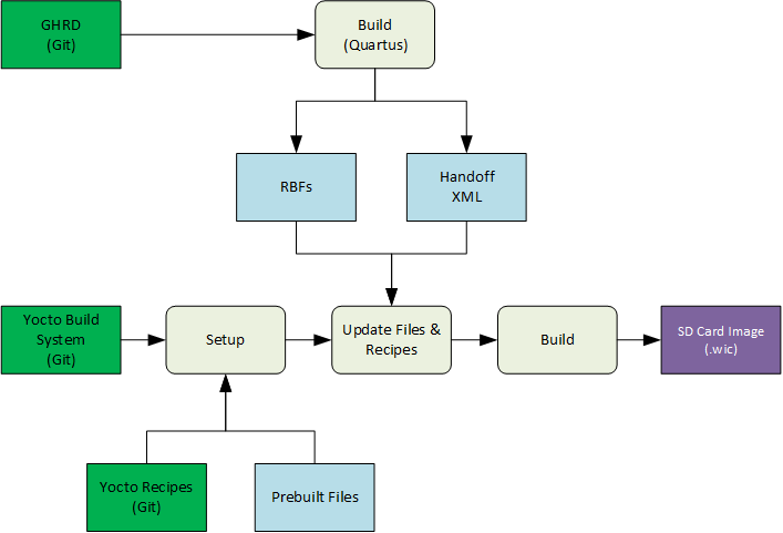 Not all the people involved in a project need to deal with the full flow. For example: