- Home
- Documentation
- Community
- Projects
- Boards
- Agilex 5 SoC
- Agilex 7 SoC
- Arria 10 SoC
- Nallatech 385A - Arria 10 FPGA Network Accelerator Card
- Nallatech 385A-SoC Accelerator Card with Arria 10 FPGA
- ALARIC Instant DevKit ARRIA 10 SoC FMC IDK by REFLEX CES
- Altera Arria 10 SoC Virtual Platform
- Altera Arria 10 SoC Board
- Nallatech 510T compute acceleration card with Intel Arria 10 FPGA
- REFLEX CES Achilles Arria 10 SoC SOM
- Terasic Arria10 SoC Board : HAN Pilot Platform
- Arria V SoC
- Cyclone V SoC
- Altera Cyclone V SoC Board
- Arrow SoCKit User Manual - July 2017 Edition
- Arrow SoCKit User Manual - November 2019 Edition
- Arrow SoCKit Evaluation Board
- Atlas-SoC Development Platform
- Critical Link MitySOM-5CSx Development Kit
- Cyclone V Ethernet driver problems
- DE10-Nano Development Board
- Terasic DE10-Standard Development Kit
- Devboards DBM-SoC1 module
- Devboards DBM-SoC2 module
- EBV SoCrates Evaluation Board
- Enclustra Mercury SA1 SoC Module
- Enterpoint Drigmorn 5
- Enterpoint Larg 2
- Altera Cyclone V SoC Development Platform
- Mpression Helio SoC Evaluation Kit by Macnica
- Mpression Sodia Evaluation Board by Macnica
- ARIES Embedded - MCV System on Module
- Mpression Borax SOM Module and Development Kit by Macnica
- Enterpoint Mulldonoch 3
- Networked Pro-Audio FPGA SoC Development Kit by Coveloz
- NOVPEK™CVLite
- NOVSOM®CV
- NOVSOM®CVLite
- NovTech IoT Octopus™
- NovTech NetLeap™
- Enterpoint Raggedstone 4
- Solectrix SMARC compliant System-on-Module
- Terasic DE1-SoC Development and Education Board
- Stratix 10 SoC
- Find a Board
- News
<<<<<<<<<< Return to WS 2 Lab Intro
LAB 1 Creating the Preloader
Generating the Preloader with BSP Editor GUI
Anytime an SoC design is generated with Qsys and compiled in Quartus an "hps_isw_handoff" folder will be generated. This folder contains configuration information which is needed by the Preloader to configure clocks, IO, and the SDRAM controller. For this lab the handoff folder has already been created for you so you do not have to run Quartus. To begin, make sure that you have the environment provided by the Embedded Command Shell which is delivered in the SoC EDS tools installation. There are a number of ways that you might get this environment applied to your development host, one way is to simply execute the "embedded_command_shell.sh" shell script that is provided in the SoC EDS tools, like this: On Linux:[~]$ <path-to-soceds-tools>/embedded/embedded_command_shell.sh [~]$Then from the embedded command shell, change into the "WS2-IntroToLinux" directory that you should have previously copied onto the local hard drive of your development host.
[~]$ cd <path-to-lab-work>/WS2-IntroToLinux
[WS2-IntroToLinux]$
Before we start the BSP Editor (Preloader Generator) program, we need to collect one piece of information about the development board that we are using for this lab work. Some of the development boards have SDRAM with ECC storage provided and some of the development boards do not. We need to set the option in the BSP Editor based on if we have ECC storage on our board or not. If you know how your board is equipped then you can proceed, if you are not sure, then execute this command in the embedded command shell to find out:
[WS2-IntroToLinux]$ grep "RW_MGR_MEM_DATA_WIDTH" ./hps_isw_handoff/soc_system_hps_0/sequencer_defines.h
#define RW_MGR_MEM_DATA_WIDTH 32
The value of the "RW_MGR_MEM_DATA_WIDTH" macro displayed above is going to equal 8, 16, 24, 32 or 40. If your macro for your board is set to 24 or 40, then your board supports ECC storage, and you will need to enable SDRAM scrubbing in the BSP Editor. If your macro for your board is set to 8, 16, or 32, then your board does not support ECC storage, and you will need to disable SDRAM scrubbing in the BSP Editor. Now start the BSP Editor (Preloader Generator) program from the embedded command shell:
[WS2-IntroToLinux]$ bsp-editor &
[WS2-IntroToLinux]$
You should see the BSP Editor GUI appear like this:
NOTE: the following images are taken from the SoC EDS 15.0.1 tools, previous tool releases may look slightly different.
 In the BSP Editor window, select File→New HPS BSP... to create a new BSP project for your board's Preloader.
NOTE: prior to the 15.0 tools release, this menu was just named New BSP
 In the New BSP window, click the ... browse button to browse to the handoff files folder:
 Select the "
 The New BSP window will have all the settings populated, based on the handoff folder. Accept the default settings and click OK. This will close the window.
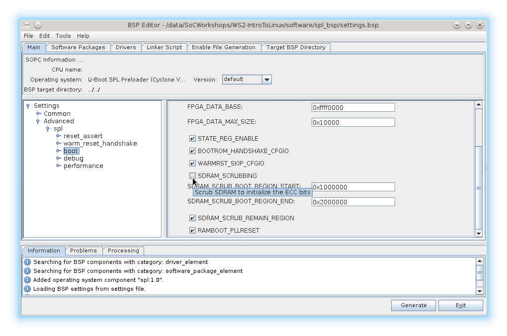
 In the BSP Editor window, we want to accept most of the defaults settings. If your development board supports ECC SDRAM storage you should select the SDRAM scrubbing option shown below, otherwise leave it unselected.
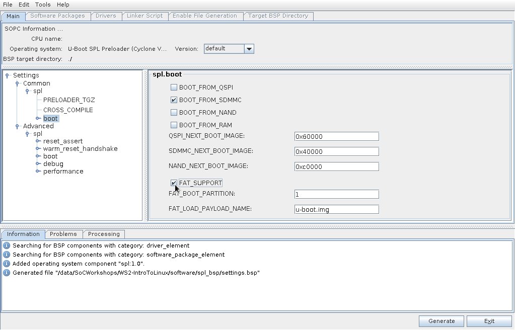
 The Preloader can load the next stage boot image from either an absolute raw address in the boot device or from a FAT partition in an SDMMC device. For this lab, you will configure the Preloader to load u-boot from a FAT partition which is partition 1 on the SD Card. Under "Settings", expand "Common" and "spl", then select "boot". In the "spl.boot" view, check the box labeled "FAT_SUPPORT". Ensure that "FAT_BOOT_PARTITION" is set to 1 and "FAT_LOAD_PAYLOAD_NAME" is set to "u-boot.img". These should be the default settings.
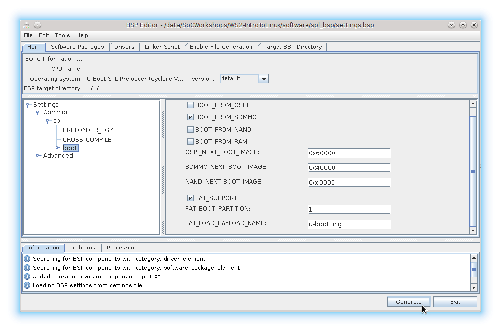
 Now click the Generate button to generate your BSP for your Preloader.
 The message panel on the bottom will indicate the status of the generation. Click Exit to close the BSP Editor.
 The following items are generated in the "
| File | Description |
|---|---|
| generated | Folder containing source code that was generated based on the information from the handoff folder |
| settings.bsp | Preloader settings file, that contains the settings from the Preloader Generator |
| Makefile | Makefile used to build the Preloader |
| preloader.ds | ARM DS-5 AE that can be used to load the Preloader |
Compiling the Preloader
In the Embedded Command Shell go to the generated Preloader folder:[WS2-IntroToLinux]$ cd software/spl_bsp/ [spl_bsp]$ ls generated Makefile preloader.ds settings.bsp uboot.ds [spl_bsp]$Run the "make" command to build the Preloader image:
[spl_bsp]$ make
[spl_bsp]$
The Makefile (also created by the Preloader Generator) performs the following steps:
- Extracts the fixed part of the Preloader source code
- Builds the Preloader executable using the fixed and the generated parts of the Preloader source code
- Converts the executable to binary, then adds the boot ROM required header to it
| File | Description |
|---|---|
| uboot-socfpga/spl/u-boot-spl | Preloader ELF file |
| uboot-socfpga/spl/u-boot-spl.bin | Preloader binary file |
| preloader-mkpimage.bin | Preloader image with the boot ROM required header |
[spl_bsp]$ ls
generated  preloader.ds            settings.bsp  uboot-socfpga
Makefile   preloader-mkpimage.bin  uboot.ds
[spl_bsp]$
Installing the new Preloader
Using the "dd" method.
We need to know with which block device our SD card is referenced on our host. This was determined when you programmed the SD card in preparation for the lab. If you did not note the SD Card block device name, refer to the instructions on the SoC SW Workshop Series SD Card Images page. Once we know which block device we want to program, we need to determine which partition we need to program. The partition that stores the preloader is the 0xA2 partition on the SD card, we can determine which partition that is by running "fdisK" like this:[spl_bsp]$ sudo fdisk -l /dev/sdb Disk /dev/sdb: 3.7 GiB, 3980394496 bytes, 7774208 sectors Units: sectors of 1 * 512 = 512 bytes Sector size (logical/physical): 512 bytes / 512 bytes I/O size (minimum/optimal): 512 bytes / 512 bytes Disklabel type: dos Disk identifier: 0x06bfaed7 Device Boot Start End Sectors Size Id Type /dev/sdb1 4096 528383 524288 256M b W95 FAT32 /dev/sdb2 528384 1048575 520192 254M 83 Linux /dev/sdb3 2048 4095 2048 1M a2 unknown Partition table entries are not in disk order. [spl_bsp]$From the above command we see that the 0xA2 partition is associated with "/dev/sdb3", so that is the partition that we will "dd" the new preloader into. If, on your host, the SD card appears as an MMC device, such as mmcblk0, the partitions will appear as mmcblk0p1, mmcblk0p2, etc. The SD Card image used for this lab will have the A2 partition on partition 3. Replace XXX with the path to the A2 partition (example: /dev/sdb3 or /dev/mmcblk0p3.) CAUTION: be absolutely certain that you have the correct device, as "dd" to the wrong device can destroy your host system.
[spl_bsp]$ sudo dd if=preloader-mkpimage.bin of=/dev/XXX3
512+0 records in
512+0 records out
262144 bytes (262 kB) copied, 0.238997 s, 1.1 MB/s
[spl_bsp]$
After we have programmed the new preloader onto our SD card we can run "sync" to ensure that all the IO is complete and then we can remove the SD card from our development host machine.
[spl_bsp]$ sync
[spl_bsp]$
Using the "alt-boot-disk-util" method.
If you are uncomfortable using the "dd" command to program the new Preloader as shown above, or if you would like a safer mechanism to accomplish this, Altera provides a utility called "alt-boot-disk-util" in the SoC EDS tools installation that attempts to provide this functionality for you. So if you follow the procedure above to determine the block device that your SD card is represented with on your development host, you can use "alt-boot-disk-util" to program your new Preloader. "alt-boot-disk-util" will inspect the device that you pass to it to ensure that it appears to be the block device with a 0xA2 partition on it and then program the new Preloader image into the proper location. You invoke it like this:[spl_bsp]$ sudo <path-to-soceds-installation>/host_tools/altera/diskutils/alt-boot-disk-util -p preloader-mkpimage.bin -a write /dev/XXXp3 Altera Boot Disk Utility Copyright (C) 1991-2014 Altera Corporation Altera Boot Disk Utility was successful. [spl_bsp]$
Using the "alt-boot-disk-util" method on Windows.
The "alt-boot-disk-util" utility is also included as part of the Altera SoCEDS and ARM Development Studio install on Windows. To run on Windows, start the Embedded Command Shell, and replace the 'X' below with the drive letter of the SD card on the Computer. The drive letter should be capitalized.alt-boot-disk-util -p preloader-mkpimage.bin -a write -d X
Running the new Preloader.
To run the new preloader on your development target.- Plug the SD card you just programmed with the new Preloader into the development target board.
- Connect the development target board to your development host machine with the USB serial cable.
- Start an appropriate terminal emulation program on your development host. See the "USB serial console interface" page for advice on this.
- Power on your development target board.
- You may need to reset the board to see the preloader messages in the terminal emulator.
Proceed to Workshop 2 Lab 2: U-Boot >>>>>>>>>>
<<<<<<<<<< Return to WS 2 Lab Intro
© 1999-2024 RocketBoards.org by the contributing authors. All material on this collaboration platform is the property of the contributing authors.
This website is using cookies. More info.
That's Fine
 RocketBoards